CSTR
Description
A continuous stirred tank reactor (CSTR) is a container used for chemical reactions. It allows the substances needed for the reaction to flow in, while the products flow out at the same time.
Status
Fully Functional
Location
MEB 2550
Standard Operating Procedure
Continuous Stirred Tank Reactor (CSTR)
SOP
Thang Tran 12-2022
Safety
- All students must wear safety glasses when working in the lab
- Never leave this equipment operating unattended
- Mix all chemicals in a fume hood
- All chemicals, solutions and standards must be stored in a sealed container. The container must be labeled with: the chemical(s) name and concentration, operator name, hazards, and date of storage
- All chemical containers must be sealed when not in use
- All unwanted material must be placed in a Nalgene container. The container must be labeled “Unwanted Material” the label must include; the chemical(s) name and concentration, the operator name and contact information, and hazards. If you have any questions regarding labeling unwanted materials, see the sign posted above the unwanted materials station.
- Only pure water can go down the drains
Equipment Description
The CSTR reactor experiment consists of the following equipment:
- Masterflex peristaltic pumps: The pumps have a switch on the rear panel; it must be set to external for the inlet pumps, in order for the computer system to control the pumps, and internal for the outlet pump to be controlled manually.
- Applikon mixer and control module. The Applikon control module has a switch on the front panel; it must be set to external (Ext).
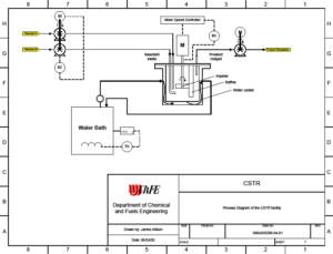
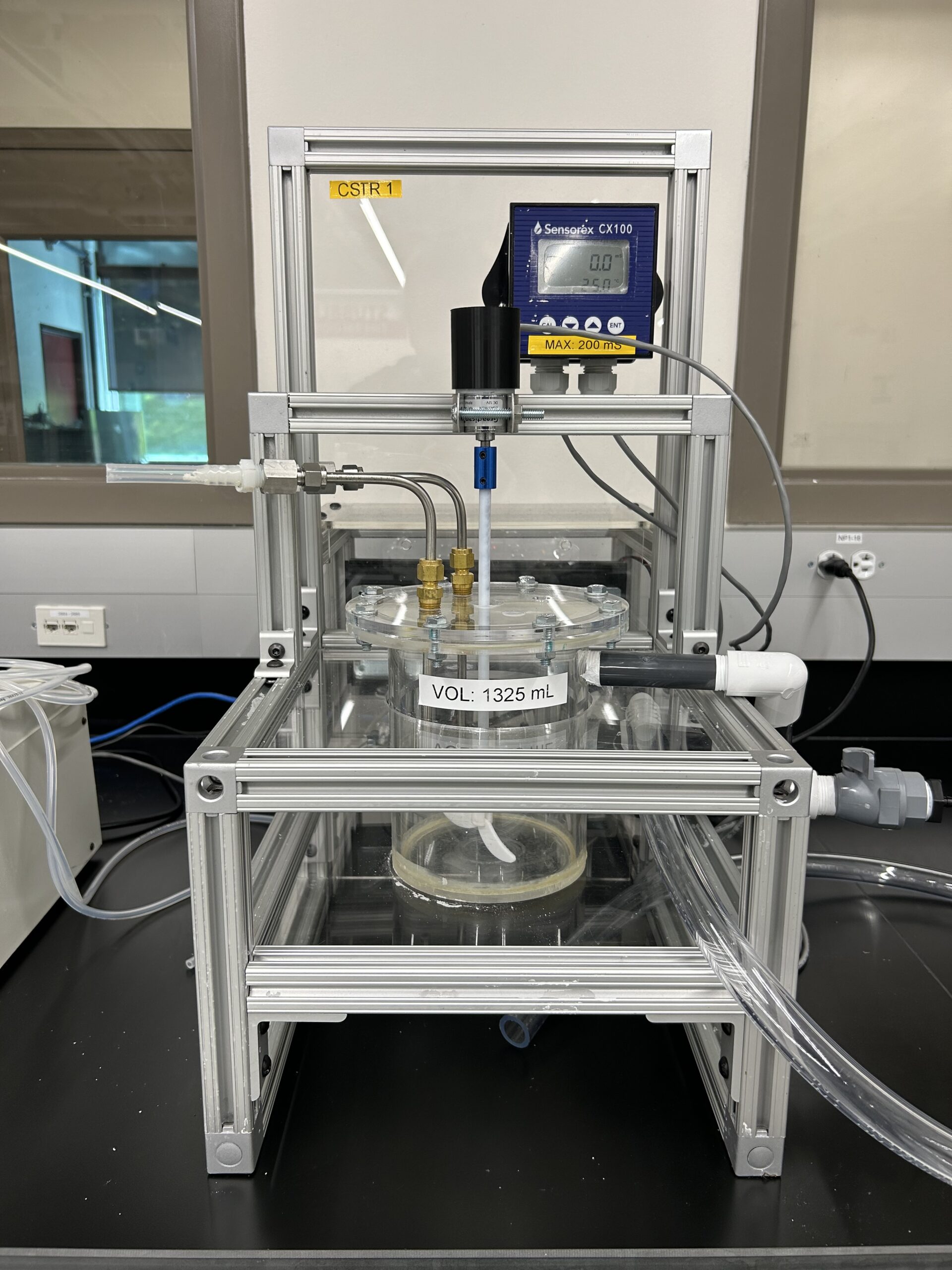
- Jacketed reactor vessel, maximum volume is 1.5 L. The reactor temperature is controlled by pumping water through the outer jacket. The temperature is set using the temperature bath controls. The temperature bath incorporates an internal pump. The jacket cooling/heating water is fed into the jacket from the bottom glass nipple connector on the glass jacket; the water exits the jacket from the upper glass nipple fitting where it returns to the temperature bath. Do not disconnect the tubing connecting the temperature bath to the reactor jacket. Once the temperature bath is turned on the water begins flowing into the See the drawing on page 5.
- Opto22 Control System:
- Data is sampled every second and stored in an Excel compatible file at C:\CSTR Data. See the section on viewing and saving your data for more information. Save your data to a flash drive. The computer is not on the network.
- Sensorex conductivity measurement system:
- Conductivity range = 0 microsiemens to 19.9 millisiemens with a resolution of 0.01 millisiemens. Optional equipment: pH and UV-ViS See lab manager for more information.
- The Opto control system allows control of 2 Masterflex pumps. The pumps may be set to a percentage output power from 0 – 100%. If desired, you may build a calibration curve to correlate percentage of power to flow. Pump flow rate depends on the tubing size and the pump speed. Control of the mixer is also set by entering a percentage of power from 0-100%. The front panel display on the Applikon control module displays the RPM of the mixer. All information displayed on the main Opto control screen is logged to a data file which can be opened in Excel. Do not open the data file while the system is logging data, doing so will stop the data log and crash the system
CSTR Procedure
- Determine what chemicals, calibration standards and measurements you will need to make.
- Determine the flowrates for your reactants.
- Refer to the section on pump specifications and tubing to help determine what tubing is appropriate for your flowrates. Be sure to use only Masterflex tubing, if you are unsure about which tubing to use check with the lab manager. The smaller the inner diameter of the tubing the lower the flowrate.
- Pumps may be calibrated using a rotameter or bucket and stopwatch.
- Place the thermocouples in the reactor at the locations where you wish to measure temperature. Take care not to place the thermocouples in the path of the impeller blades inside the reactor vessel.
- To measure the temperature of the feed or outlet streams you may place a thermocouple in a tee fitting placed in the tubing.
- Install the tubing in the peristaltic pumps. By using the same size tubing in both heads of one of the dual –head pumps you can achieve two identical flow rates.
- Place the reactant feed tubing into the reactor. You may place the tubing in any of the ports located on the top of the reactor head-plate.
- Setup a pump to pull the solution out of the reactor (outlet pump). You may install the outlet tube anywhere in the head-plate. Take care that the tubes don’t interfere with the impeller in the reactor.
- Determine what method you will use to measure the product stream, your options are measuring pH, conductivity or you may measure the transmission of light using a Uv-Vis spectrophotometer. Once you have determined a measurement technique, run the appropriate calibration standards to verify the accuracy of your measuring system.
- Power up all equipment:
- Switch on the power to the pumps using the grey toggle switch located on the front Switch to the right or left to control the pump direction, the center position is off for old pumps. For newer models, the power switch is located in the back of the pump.
- Switch on the Applikon control module using the switch on the front panel.
- Switch on the temperature bath by pushing the ON button on the front panel.
- The Sensorex conductivity module does not have a switch, it is always on.
- Do not touch the Opto22 control hardware located above the reactor.
- Using the conductivity measurement system:
- The conductivity probe is enclosed in a tee fitting which is mounted on a ring stand next to the reactor vessel. The probe connects to the conductivity transmitter (Sensorex Model CX 100) mounted on the CSTR frame.
- Do not adjust the position of the probe within the tee. It is set at the correct depth and angle, adjusting the probe will disrupt data collection.
- Calibrating the conductivity system:
- Determine the range of conductivity you want to measure, the specifications for the conductivity system are listed in this document.
- Collect the required conductivity standards.
- Setup a pump to pump just enough conductivity standard to fill the tubing and the tee; this is typically about 300-500 ml.
- Place the conductivity standard in a beaker, place a small section of tubing into the beaker and then place the tubing in a pump head. Connect the other end of the tubing to the bottom inlet of the tee. This will pump the conductivity standard into the tee / probe assembly, filling it from the bottom.
- Now connect another section of tubing to the outlet at the top of the tee. Place the other end of this tubing into the beaker containing the conductivity standard. This completes the pump circuit allowing you to continuously pump conductivity standard solution through the tee/probe assembly.
- Once the reading of the CX 100 conductivity meter as well as the corresponding conductivity reading on the computer display are reading the value of the conductivity standard you can stop the pump and disassemble the calibration setup.
- Do not attempt to adjust the calibration setting on the CX100 conductivity meter. Consult the lab manager if you feel that the meter requires calibration.
- Once you have confirmed the calibration of the conductivity probe connect the bottom of the tee to the outlet pump of the reactor.
- See the lab manager for assistance with other measuring devices such as pH and UV-Vis.
- Determine the amount of feed stock you will require.
- Mix all chemicals / feedstock dilutions in a fume hood.
- Place your feedstock in 8 liter Nalgene containers available in the “A” lab on the shelf above the chemical storage cabinets.
- Feed the outlet stream of the system into another Nalgene container.
- Verify that the feed and drain pumps are connected properly.
- There is a floor balance located next to the computer that may be used to weigh your solutions.
How to view and save data in Excel
- Do not try to view your data while the system is running, this will cause it to stop data collection
- Save data to a flash drive after each trial
- If you have any questions, please see the Lab assistant
If you are running one trial:
- Once all your required data has been collected, exit the Opto system
- Open Excel, click “Open” and navigate to the correct data folder specified in the SOP
- In the bottom of the Excel window, click on the drop-down window and select All Files this will display the data files collected organized by date
- Double-click on the file you wish to open, the Text Import Wizard will open
- Select Delimited then click Next, then select Comma Delimited and click Next. Select the General Data format option and click Finish. The data should now be displayed in Excel
- Save your data to the flash drive by clicking Save As and selecting your flash drive as the destination. Ensure you label your data properly and thoroughly to avoid confusion
- Eject the flash drive.
- Follow the rest of the shutdown procedure specified in the equipment SOP
If you are running several trials in one day:
- Leave the Opto system running
- Open File Explorer and navigate to the correct data folder specified in the SOP for your equipment
- Organize by date if not already done so, your data should appear at the top of the list
- Right click on your data file and “cut” the file (or press Ctrl X after clicking once on the file)
- Note: this will effectively cut the data that was collected up to that point into a file and begin a new data collection (a new file will be created with the same name as the file you cut) as soon as it is cut
- Paste the file to a flash drive and rename with the proper label, ensure you are labeling your data thoroughly to avoid confusion
- Eject the flash drive and save to your personal device
- To open in Excel on your personal device:
- Open Excel, click Open and navigate to the saved data on your flash drive or device
- In the bottom of the Excel window, click on the drop-down window and select All Files this will display the data files collected organized by date
- Double-click on the file you wish to open, the Text Import Wizard will open
- Select Delimited then click Next, then select Comma Delimited and click Next. Select the General Data format option and click Finish. The data should now be displayed in Excel
Shutdown
- Drain the tank and store any solution you wish to save in a properly labeled Nalgene container. Consult the lab manager regarding chemical storage.
- Flush the system with tap water for 5 minutes, or until the conductivity meter reads <100 microsiemens and then drain and dispose of the water down the drain.
- Label all containers.
- Properly dispose of any unwanted material, consult the lab manager for guidance.
- Switch off the temperature bath.
- Switch off the power to the pumps; this is the toggle switch on the front panel, the center position is off, or the switch in the back of the pump.
- Turn off the power switch located on the front of the Applikon control module.
- Do not attempt to switch off the Sensorex conductivity module.
- Exit the Opto control software, Do Not Shutdown the computer.
- Save your data to a flash drive, the computer is not on the network