- All Standard Operating Procedures
- UOL – Gas Absorption Column SOP
Standard Operating Procedure
Introduction
A gas absorption column is used to separate specific components from a gas mixture by absorbing them into a liquid. This separation is based on interphase mass transfer controlled largely by rates of diffusion. The target gas component is transferred from the gas phase into the liquid phase (flowing counter currently), typically through a packing or tray system that enhances contact between the two phases. This experiment aims to explore the efficiency of gas absorption under varying conditions.
Do not proceed with testing without following all safety procedures. A basic list of safety considerations is provided in Section II of this SOP.
Safety
- All students must wear safety glasses when working in the lab.
- Never leave this equipment operating unattended.
- Mix all chemicals in a fume hood.
- All chemicals, solutions, and standards must be stored in a sealed container. The container must be labeled with chemical(s) name and concentrations, operator/user’s name, hazards, and date of storage. Confirm storage location with the lab manager.
- All chemical Containers must be sealed when not in use.
- All unwanted material must be placed in an appropriate container. The container must be labeled “Unwanted Material.” The label must include the chemical(s) name and concentration, the operator/user’s name and contact information. See the sign posted above the unwanted materials table in the Senior Lab.
- Only pure water can go down he drains.
- Compressed gas cylinders should only be operated by lab managers as they can be very dangerous when not used correctly.
Equipment Description
The gas absorption column consists of the following components, as shown in Figures 1 through 5. Figures 1 and 2 are extracted from the Users’ Manual, showing front and rear views of the apparatus. Figure 3 is a photograph of the equipment in the laboratory with components labelled. Figure 4 labels valves that you will need to manipulate when using the equipment. Figure 5 is a photograph of two CO2 analyzers for use in your experiments.
- Column filled with Raschig rings. A Raschig ring is a hollow, open-ended cylinder, approximately equal in length and diameter, used as a components in a packed bed within columns. The specifications of the column here are as follows.
Column Diameter………………………………………………………………………………………………… 80 mm
Column Length………………………………………………………………………………………………………. 1.4 m
Raschig Rings Specific Area (10 mm x 10 mm)……………………………………………….. 440 m2/m3
Packing Volume…………………………………………………………………………………………………… 7 liters
- Centrifugal Blower
- Liquid Pump
- Masterflex Peristaltic Pump
- Valves for operation of the column are shown in Figure 4.
- Two CO2 analyzers, as described below (refer to Figure 5)
Alpha Omega Instruments 9510 Series
- 100-300 ml/min flow range
- 0 psig maximum operating pressure
- 0-25 % CO2 concentration range
Alpha Omega Instruments 9500 Series
- 5-1 L/min flow range
- 0 psig maximum operating pressure
- 0-25 % CO2 concentration range
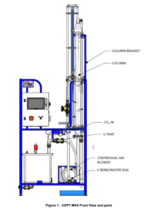
Figure 1. This is a front view, with
|
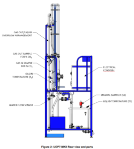
Figure 2. Rear view and |
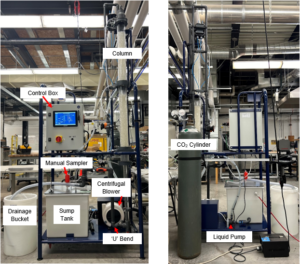
Figure 3. Equipment locations on the gas absorption column.
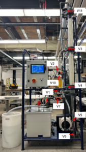
Figure 4. Valve locations on the gas absorption column.
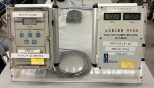
Figure 5. CO2 analyzers used for testing gas absorption. 9510 Series (Left) and 9500 Series (Right).
Procedures
A brief description of each control parameter is provided below. For a more detailed discussion of system operation, please consult the operator’s manual.
CO2 Analyzer Calibration
- Using a crescent wrench, remove the tubes attached to the back of both CO2 analyzers. Make sure to keep track of which tube goes to which analyzer
- Independently for each analyzer, attach the provided CO2 gas calibration standard to the back of one of the CO2 analyzers.
Note: Do not overtighten the connection between the analyzer and the tubes to avoid damaging the fittings. Tighten until it is finger tight and then use the crescent wrench to tighten an additional quarter turn.
- Open the CO2 gas calibration standard by pushing the knob on the cylinder in and then turning it until it is caught under the lip that will hold it open.
- Wait till the reading on the analyzer stabilizes and then adjust the readings to match the standard using the appropriate method below.
- Series 9510
- Open the protective cover.
- Press all three alarm buttons simultaneously to start calibration.
- Use the up and down arrows to adjust the reading until it matches your calibration standard.
- Press all three alarm buttons simultaneously to set your calibration.
- Close the protective cover.
- Series 9500
- Loosen the hex screw on the knob attached to the right of the analyzer.
- Turn the knob to adjust the reading until it matches your calibration standard.
- Retighten the hex screw on the knob
- Series 9510
- Close the CO2 gas calibration standard by pushing the knob on the cylinder in and then turning it till it pops back out.
- Remove the gas calibration standard from the back of the CO2 analyzer.
- Repeat steps 2-6 for the other CO2 analyzer.
- Reattach the tubes from the gas absorption column to the CO2 analyzer it was previously attached to.
Determining Gas Absorption
- Take detailed notes during your experiments, documenting failed and successful tests.
- Verify that the drain pipe is connected to V7 (Figure 5) and that the end of the tube is placed in the drainage bucket (Figure 3).
- Fill the sump tank with clean cold water by turning on the water supply connected to the float valve located behind and to the left of the gas absorption column.
- Switch on the console. Readings of flows and CO2 concentration should show typically zero values. Values for temperature of gas, temperature of water and differential pressure in the top and bottom sections of the column should also be seen on the display.
- Completely close the CO2 flow control valve V1. Do not proceed past this step till you have consulted with the lab manager.
- Open the isolating valve on the CO2 cylinder. THIS STEP WILL BE DONE BY THE LAB MANAGER.
- Turn on the peristaltic pump near the water supply valve and set its speed to ensure that the drainage bucket doesn’t overflow. Note: DO NOT leave the peristaltic pump running if there is no water entering the drainage bucket. Running it dry will cause the pump to “burn through” the tubing.
- Switch on the liquid pump by setting the percent power on the control box. Gradually open flow control valve V10 and confirm that water is delivered to the top of the column; adjust valve V10 until you reach your desired water flow rate. The manual suggests 4 L/min. discuss this with the Lab Manager. Leave the pump running with water flowing down through the Raschig rings.
- Close the air flow control valve V2. Close the gas sampling valves V3, V4, and V11 on the absorption column. Check that the flow control valve V7 in the discharge pipe from the ‘U’ bend (Figure 3) is fully open.
- Switch on the centrifugal air blower using the appropriate switch on the control box. Gradually open the air flow control valve V2 and check that air flows upwards through the column and exits at floor level from the vertical next to V6. Adjust valve V2 until you reach your desired air flow rate. The manual suggests 80 L/min. Discuss this with the Lab Manager.
- Adjust valve V7, if necessary, to maintain a liquid seal in the ‘U’ bend; gradually close valve V7, if necessary, so that air does not escape via the ‘U’ bend.
- Open the sampling valves V3, V4, and V11 on the column. Check that the two reading for pressure drop on the display indicate the pressure drop across the column.
- Gradually open the CO2 control valve V1 until you reach your desired CO2 flow rate.
Determining Liquid Absorption
- Remove the Drain pipe connected to V7 and replace it with the circulation pipe that returns water to the tank as seen in figure 6.
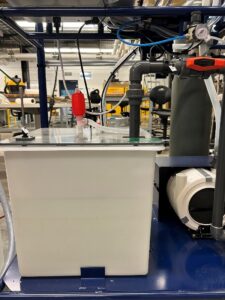
Figure 6. Circulation pipe connected to the sump tank for liquid absorption testing.
2. Fill the sump tank approximately three-quarters full with your solution.
3. Switch on the console. Readings of flows and CO2 concentration should show typically show zero values. Values for temperature of gas, temperature of water and differential pressure in the top and bottom sections of the column should also be seen on the display.
4. Completely close the CO2 flow control valve V1.
Do not proceed past this step till you have consulted with the lab manager.
5. Open the isolating valve on the CO2 cylinder. THIS STEP WILL BE DONE BY THE LAB MANAGER.
6. Switch on the liquid pump by setting the percent power on the control box. Gradually open flow control valve V10 and confirm that your solution is delivered to the top of the column; adjust valve V10 until you reach your desired flow rate.
7. Close the air flow control valve V2. Close the gas sampling valves V3, V4, and V11 on the absorption column. Check that the flow control valve V7 in the discharge pipe from the ‘U’ bend is fully open.
8. Switch on the centrifugal air blower using the appropriate switch on the control box. Gradually open the air flow control valve V2 and check that air flows upwards through the column and exits at floor level from the vertical next to V6. Adjust valve V2 until you reach your desired air flow rate.
9. Adjust valve V7 if necessary, to maintain a liquid seal in the ‘U’ bend; gradually close valve V7, if necessary, so that air does not escape via the ‘U’ bend.
10.Open the sampling valves V3, V4, and V11 on the column. Check that the two reading for pressure drop on the display indicate the pressure drop across the column.
11.Gradually open the CO2 control valve V1 until you reach your desired CO2 flow rate.
Caution: As the solution used is caustic it is essential that the column is not allowed to flood. The air supply should be turned off IMMEDIATELY if any liquid is present in the clear tube above the top of the column.
12.After 15 minutes of steady operation, take samples at 20 minute intervals simultaneously from V5 and the sump tank using the manual sampler. It is recommended that a 250 ml sample is taken so analysis can be done in duplicates.
Shutdown
- Close the air flow control valve V2 and switch off the air compressor. Fully close the water flow control valve V10 and switch off the liquid pump.
- Let the peristaltic pump finish emptying the drainage bucket, then move the peristaltic pump tube into the sump tank to empty the sump tank.
Note: If any solution other than water is inside the sump tank make sure to place the end of the peristaltic pump tube in the drain unto a collection container instead. Then properly dispose of the used chemicals.
- Turn off the peristaltic pump and close the water supply valve.
- Close the isolating valve on the CO2 THIS STEP WILL BE DONE BY THE LAB MANAGER.